


Downloads
Product Catalog
GIK Acoustics 2019 Spring Catalog UK
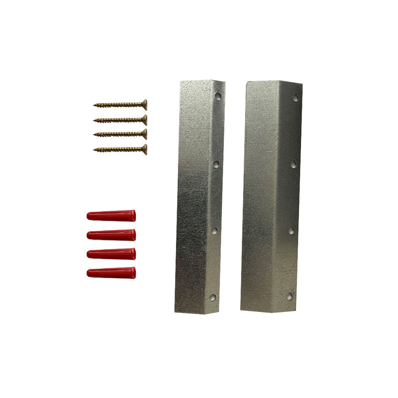
Instructions
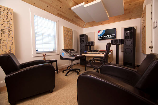
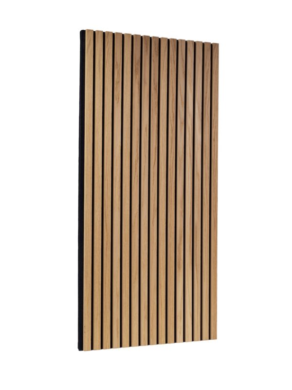
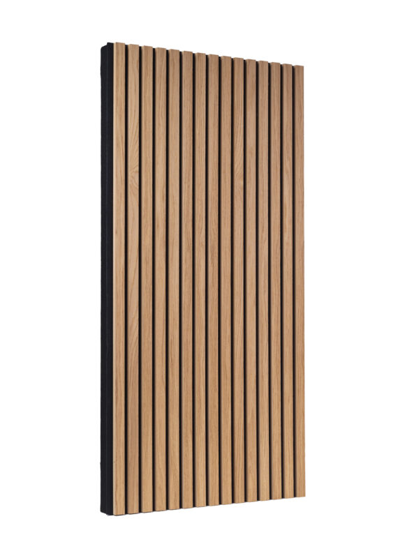
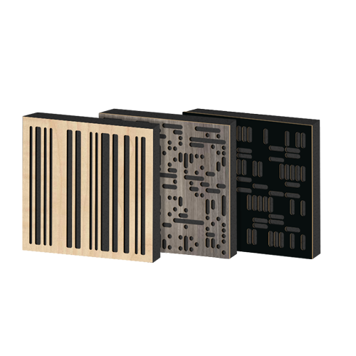
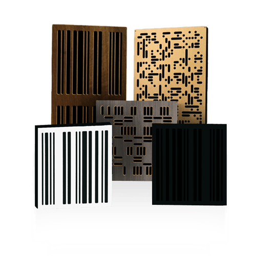
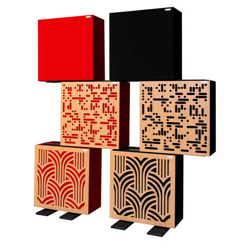
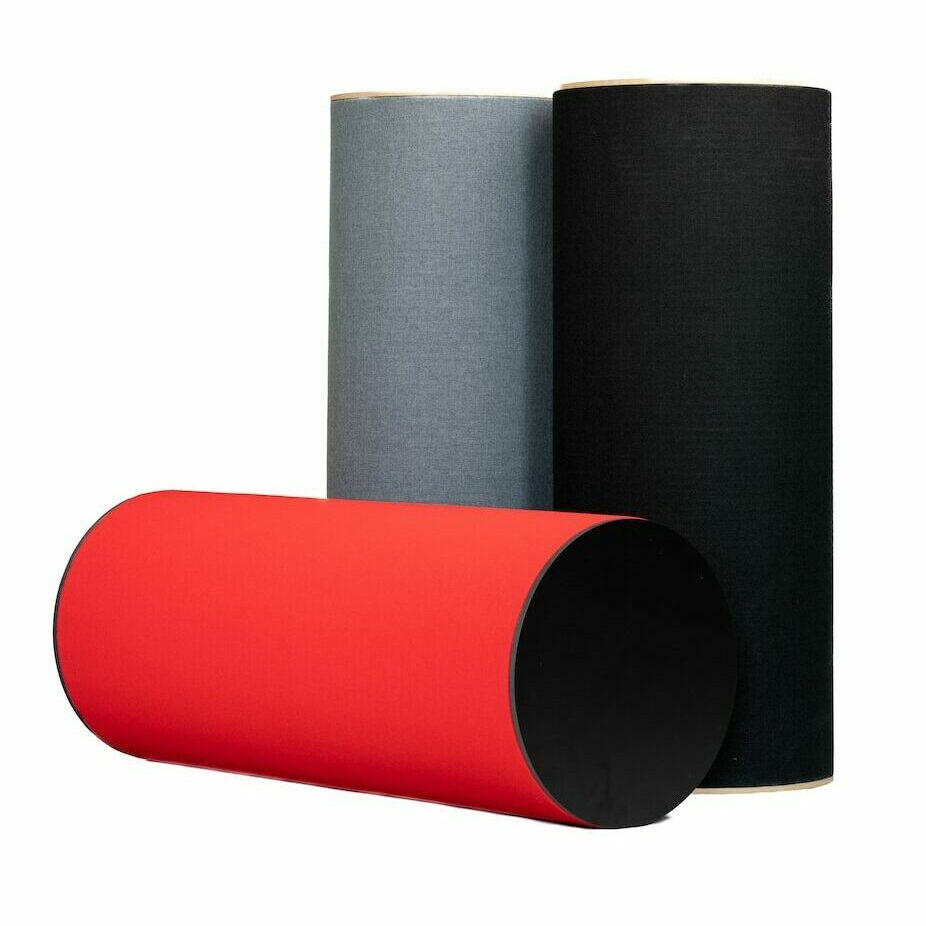
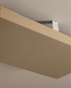
Acoustic Panels
Spot Panel (50mm)
Full Test Results
Frequency Graph
242 Acoustic Panel
Datasheet
Salford Test Results
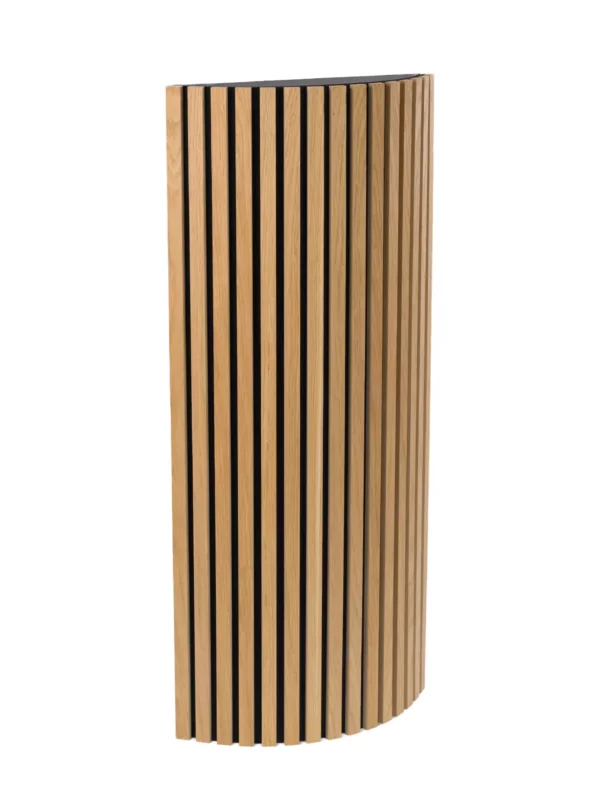
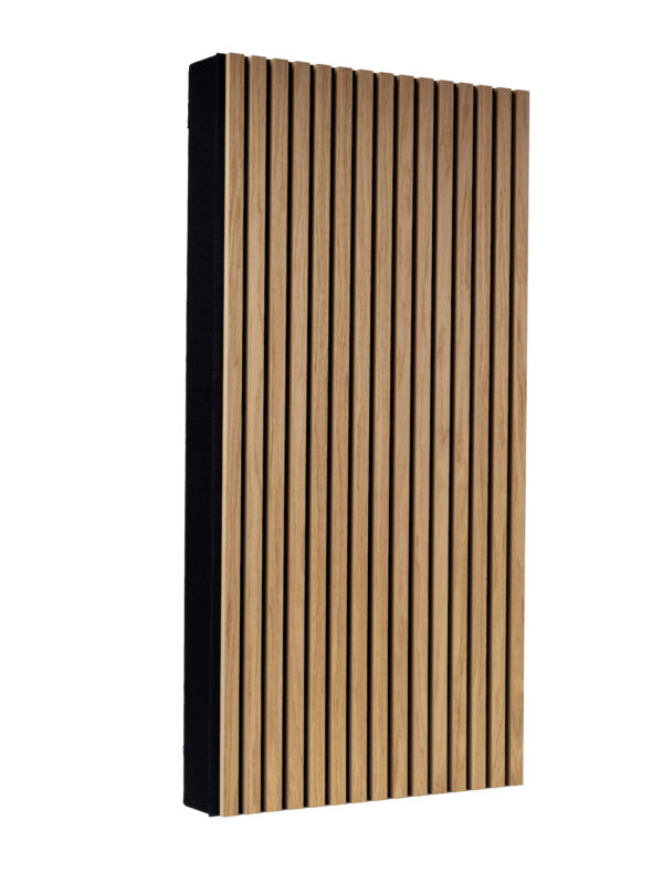
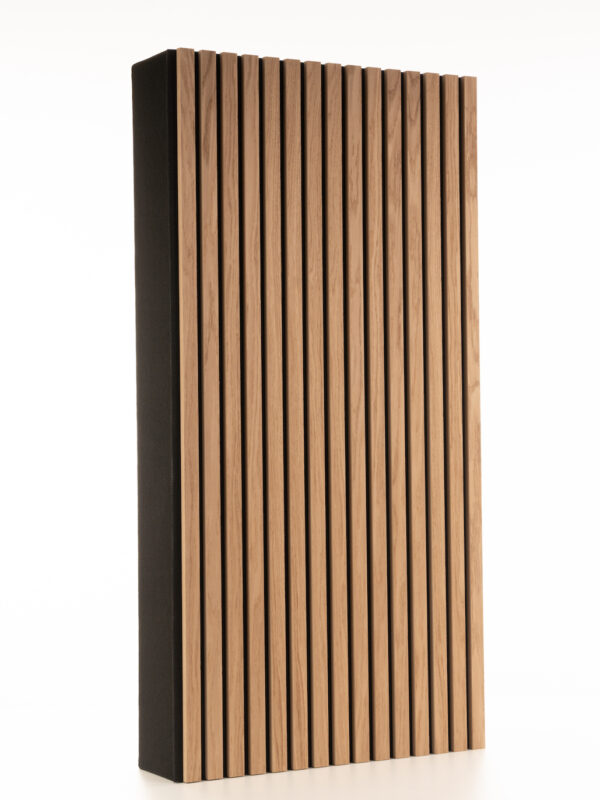
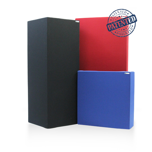
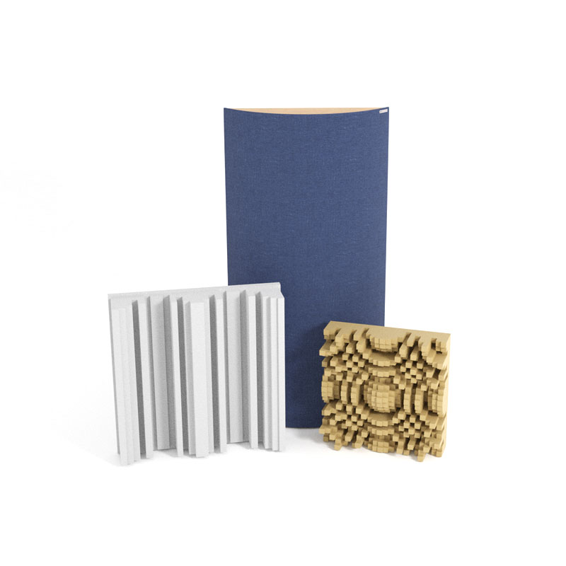
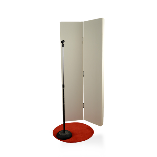
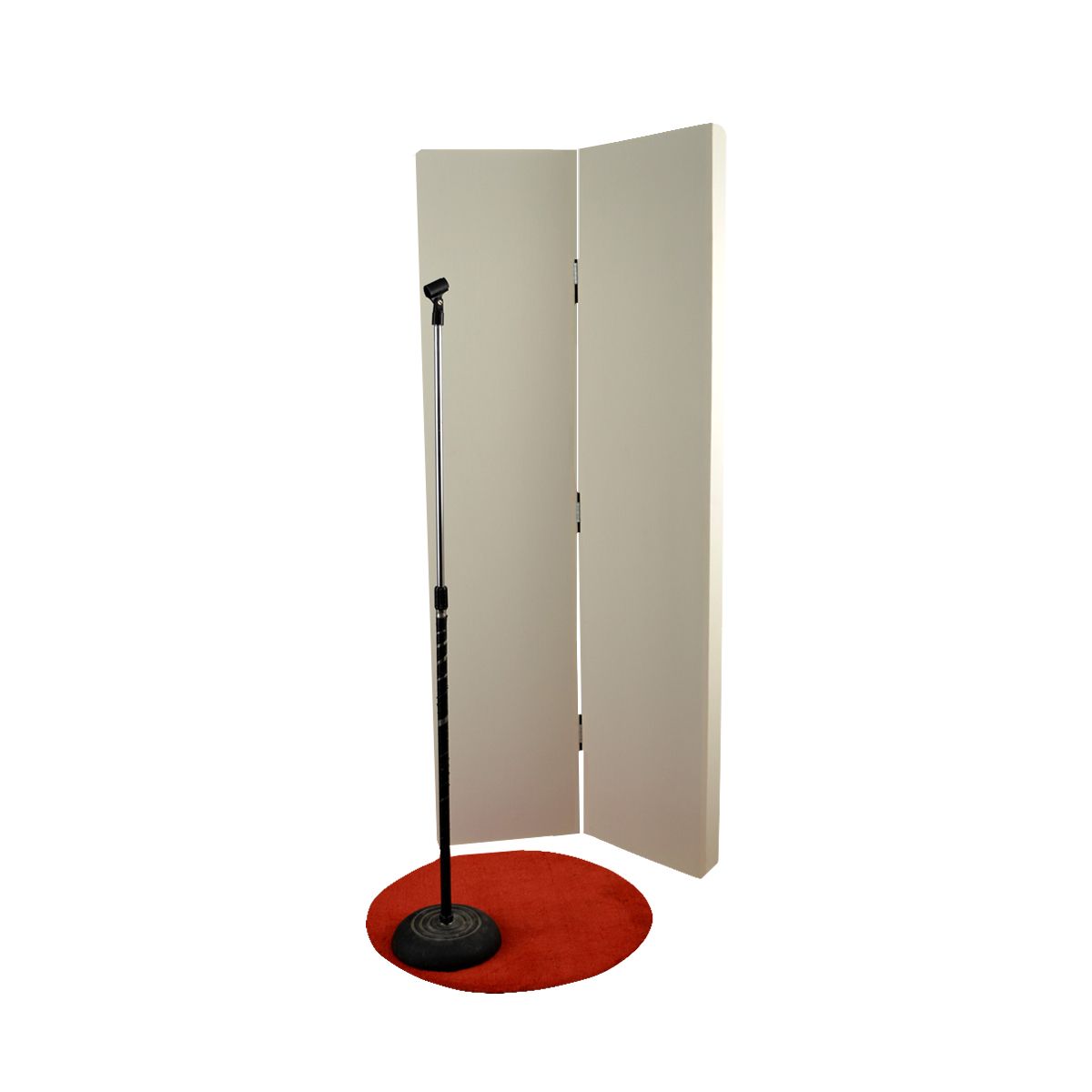
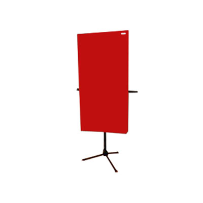
FreeStand Acoustic Panel
Full FreeStand Acoustic Panel Report
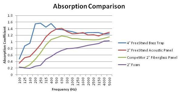
Comparison Chart between Freestand Acoustic Panel (2″) and Bass Trap (4″)
Bass Traps
244 Bass Trap with FlexRange Technology
Datasheet
RAL Full Range Test
RAL Test with Range Limiter
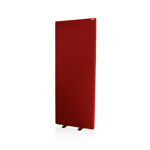
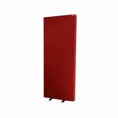
FreeStand Bass Trap
Salford Report
Comparison Chart between Freestand Acoustic Panel (2″) and Bass Trap (4″)
Monster Bass Trap with FlexRange Technology
Datasheet
RAL Full Range Test
RAL Test with Range Limiter.
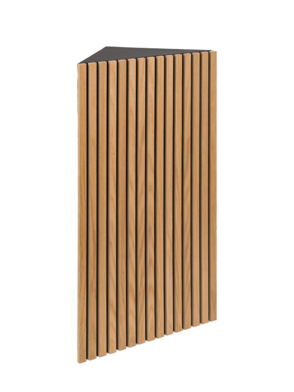
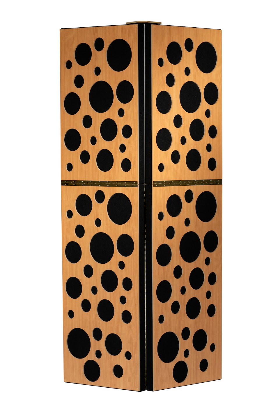
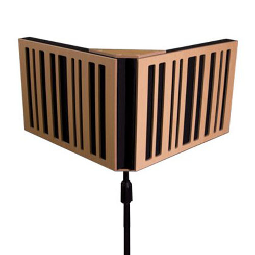
Tri-Trap Corner Bass Trap
J-Mount Report
Soffit Bass Trap
J-Mount Test
Test with Range Limiter
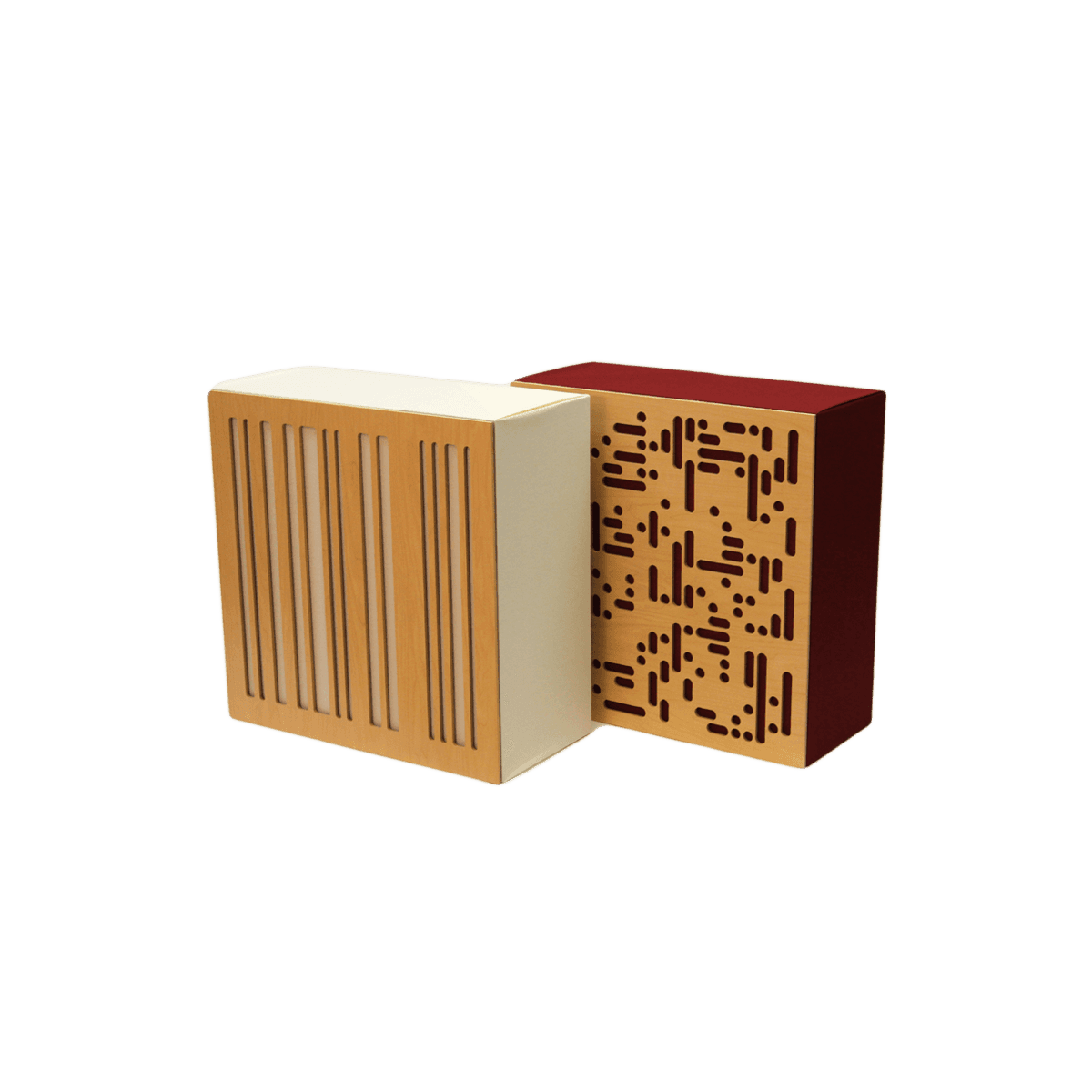
Alpha Series
2A Alpha Series Acoustic Panel
Salford A Mount Test
Salford Corner Mount Test
4A Alpha Series Bass Trap
RAL A-Mount Test
6A Alpha Series Bass Trap
Salford A Mount Test
Salford Corner Mount Test
CT Alpha Series Corner Bass Trap
Salford Test Results Corner CT Alpha Bass Trap
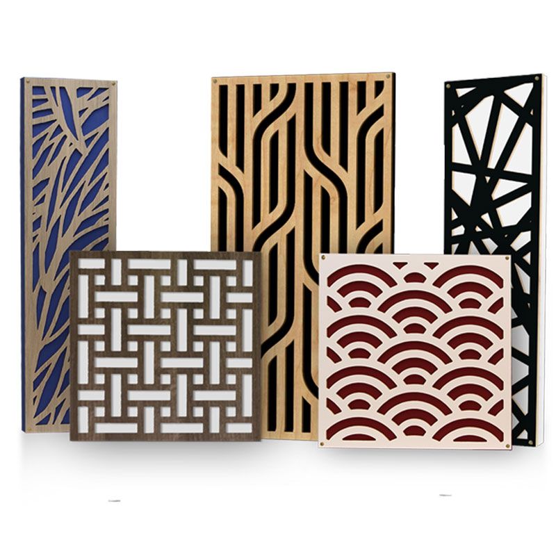
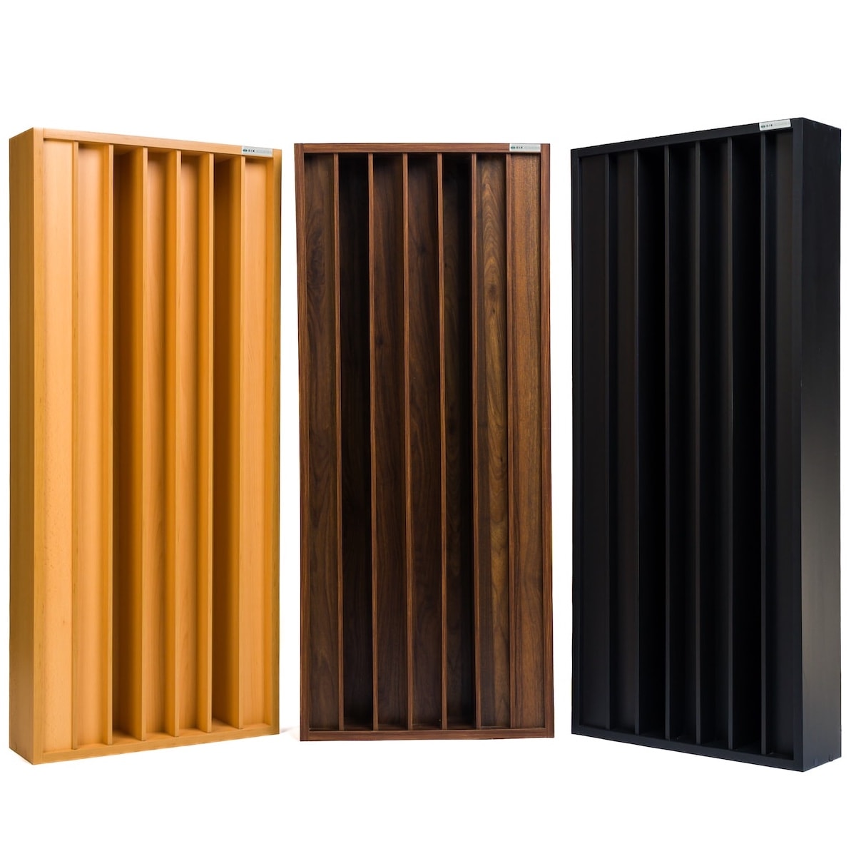
Impression Series
100mm Impression Series Panels
A Mount Report
D Mount Report
J Mount Report
Scopus Series
T40 Scopus Tuned Membrane Bass Trap
A Mount Report
J Mount Corner Report
Absorption Graph
T70 Scopus Tuned Membrane Bass Trap
Absorption Graph
T100 Scopus Tuned Membrane Bass Trap
RAL A Mount Report
RAL J Mount Corner Report
Absorption Graph
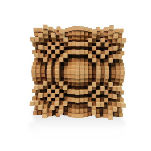
Unique Combination Diffusors/Absorbers
PolyFusor Absorber/Diffusor
Wall A-Mount Report
Corner J-Mount Report
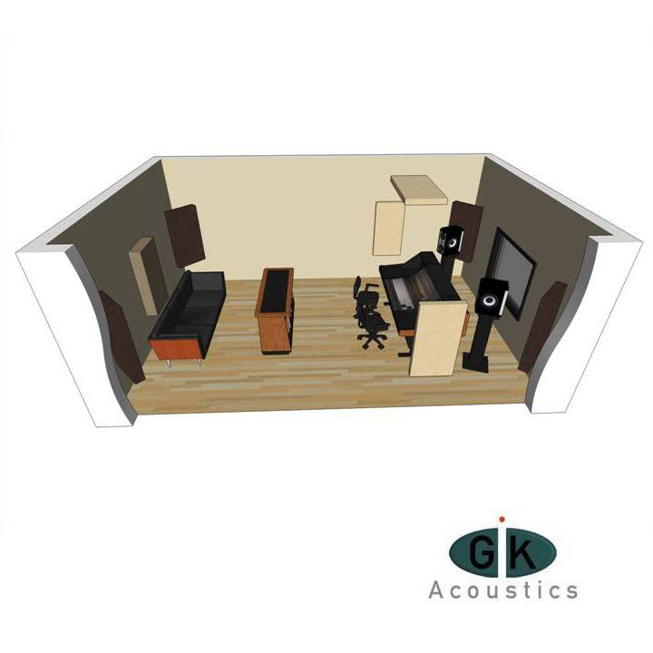
Testing
We use independent laboratories for testing:
Riverbank Acoustical Laboratories™
An accredited by the U.S. Department of Commerce, National Institute of Standards and Technology (NIST) under the National Voluntary Laboratory Accreditation Program (NVLAP) as an ISO 17025:2005 Laboratory (NVLAP Lab Code: 100227-0) and for this test procedure. The test reported in this document conformed explicitly with ASTM C423-09a: “Standard Test Method for Sound Absorption and Sound Absorption Coefficients by the Reverberation Room Method.” The specimen mounting was performed according to ASTM E795-05(2012): “Standard Practices for Mounting Test Specimens During Sound Absorption Tests.” A description of the measuring procedure and room qualifications is available upon request.
University of Salford’s Acoustic Test Calibration Laboratory
As part of their internationally renowned acoustics measurement facility, the University of Salford’s Acoustic Test & Calibration Laboratory provides an independent, service for acoustic consultancies, local authorities, construction, product design and other acoustic-related industries. See their UKAS scope here for Calibration and Testing.
Interpretation
In order to demonstrate the effectiveness of our products, we chose to record the best, most accurate measurement of absorption from each laboratory used. In some cases, it is known as the Absorption Coefficient, while in others, it is explained as the Random Incidence Equivalent Absorption Area. We also may use the more commonly known Noise Reduction Coefficient (NRC), which is the measure (NRC) from 0 to 1. 0 being absolute reflection and 1 being absolute absorption of sound waves into the material. Here, we are measuring absorption both among time and frequency.
Mount Types Tested:
Type A Mounting:
The test specimen was laid directly against the test surface. The perimeter edges were exposed, as would be typical of an actual installation of this specimen.
Type D-100 Mounting:
The test specimen was mounted on 100 mm (3.937 in.) thick wood furring strips spaced 300 mm (12 in.) on centers and laid directly against the test surface. The furring strips produced a 100 mm (3.937 in.) thick air space behind the test specimen. The perimeter was sealed with wood and metal framing.
Type J Mount:
The specimen is a set of sound absorbing units installed with one surface in direct contact with the test surface and another in direct contact of the side wall of reverberation chamber. This approximates the corner mounting method typical of the actual product installation. The units were evenly spaced along the walls of the chamber (3 on North wall, 2 on South wall, 2 on the East wall and 1 on West wall).